PCIe Fundamentals Server Storage I/O Network Essentials

Updated 8/31/19

PCIe Fundamentals Server Storage I/O Network Essentials

PCIe fundamentals data infrastructure trends

This piece looks at PCIe Fundamentals topics for server, storage, I/O network data infrastructure environments. Peripheral Computer Interconnect (PCI) Express aka PCIe is a Server, Storage, I/O networking fundamentals component. This post is an excerpt from chapter 4 (Chapter 4: Servers: Physical, Virtual, Cloud, and Containers) of my new book Software Defined Data Infrastructure Essentials – Cloud, Converged and Virtual Fundamental Server Storage I/O Tradecraft (CRC Press 2017) Available via Amazon.com and other global venues. In this post, we look various PCIe fundamentals to learn and expand or refresh your server, storage, and I/O and networking tradecraft skills experience.

PCIe fundamentals Server Storage I/O Fundamentals

PCIe fundamental common server I/O component

Common to all servers is some form of a main system board, which can range from a few square meters in supercomputers, data center rack, tower, and micro towers converged or standalone, to small Intel NUC (Next Unit of Compute), MSI and Kepler-47 footprint, or Raspberry Pi-type desktop servers and laptops. Likewise, PCIe is commonly found in storage and networking systems, appliances among other devices.

For example, a blade server will have multiple server blades or modules, each with its motherboard, which shares a common back plane for connectivity. Another variation is a large server such as an IBM “Z” mainframe, Cray, or another supercomputer that consists of many specialized boards that function similar to a smaller-sized motherboard on a larger scale.

Some motherboards also have mezzanine or daughter boards for attachment of additional I/O networking or specialized devices. The following figure shows a generic example of a two-socket, with eight-memory-channel-type server architecture.

PCIe fundamentals SDDC, SDI, SDDI Server fundamentals
Generic computer server hardware architecture. Source: Software Defined Data Infrastructure Essentials (CRC Press 2017)

The above figure shows several PCIe, USB, SAS, SATA, 10 GbE LAN, and other I/O ports. Different servers will have various combinations of processor, and Dual Inline Memory Module (DIMM) Dynamic RAM (DRAM) sockets along with other features. What will also vary are the type and some I/O and storage expansion ports, power and cooling, along with management tools or included software.

PCIe, Including Mini-PCIe, NVMe, U.2, M.2, and GPU

At the heart of many servers I/O and connectivity solutions are the PCIe industry-standard interface (see PCIsig.com). PCIe is used to communicate with CPUs and the outside world of I/O networking devices. The importance of a faster and more efficient PCIe bus is to support more data moving in and out of servers while accessing fast external networks and storage.

For example, a server with a 40-GbE NIC or adapter would have to have a PCIe port capable of 5 GB per second. If multiple 40-GbE ports are attached to a server, you can see where the need for faster PCIe interfaces come into play.

As more VM are consolidated onto PM, as applications place more performance demand either regarding bandwidth or activity (IOPS, frames, or packets) per second, more 10-GbE adapters will be needed until the price of 40-GbE (also 25, 50 or 100 Gbe) becomes affordable. It is not if, but rather when you will grow into the performance needs on either a bandwidth/throughput basis or to support more activity and lower latency per interface.

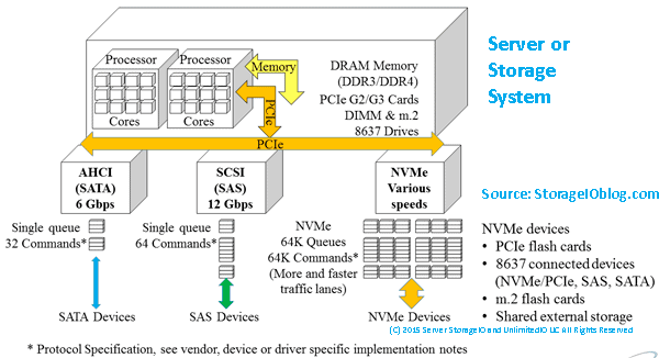
PCIe is a serial interface specified for how servers communicate between CPUs, memory, and motherboard-mounted as well as AiC devices. This communication includes support attachment of onboard and host bus adapter (HBA) server storage I/O networking devices such as Ethernet, Fibre Channel, InfiniBand, RapidIO, NVMe (cards, drives, and fabrics), SAS, and SATA, among other interfaces.

In addition to supporting attachment of traditional LAN, SAN, MAN, and WAN devices, PCIe is also used for attaching GPU and video cards to servers. Traditionally, PCIe has been focused on being used inside of a given server chassis. Today, however, PCIe is being deployed on servers spanning nodes in dual, quad, or CiB, CI, and HCI or Software Defined Storage (SDS) deployments. Another variation of PCIe today is that multiple servers in the same rack or proximity can attach to shared devices such as storage via PCIe switches.

PCIe components (hardware and software) include:

  • Hardware chipsets, cabling, connectors, endpoints, and adapters
  • Root complex and switches, risers, extenders, retimers, and repeaters
  • Software drivers, BIOS, and management tools
  • HBAs, RAID, SSD, drives, GPU, and other AiC devices
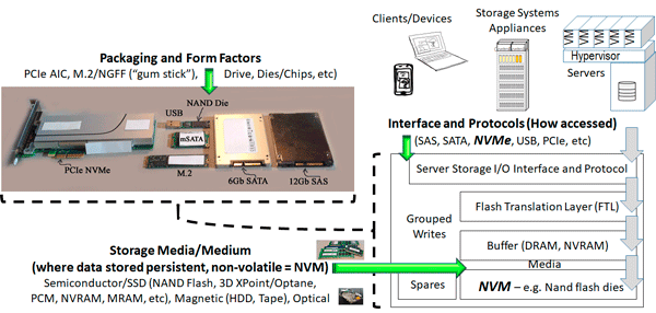
  • Mezzanine, mini-PCIe, M.2, NVMe U.2 (8639 drive form factor)

There are many different implementations of PCIe, corresponding to generations representing speed improvements as well as physical packing options. PCIe can be deployed in various topologies, including a traditional model where an AiC such as GbE or Fibre Channel HBA connects the server to a network or storage device.

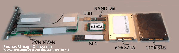
Another variation is for a server to connect to a PCIe switch, or in a shared PCIe configuration between two or more servers. In addition to different generations and topologies, there are also various PCIe form factors and physical connectors (see the following figure), ranging from AiC of various length and height, as well as M.2 small-form-factor devices and U.2 (8639) drive form-factor device for NVMe, among others.

Note that the presence of M.2 does not guarantee PCIe NVMe, as it also supports SATA.

Likewise, different NVMe devices run at various PCIe speeds based on the number of lanes. For example, in the following figure, the U.2 (8639) device (looks like a SAS device) shown is a PCIe x4.

SDDC, SDI, SDDI PCIe NVMe U.2 8639 drive fundamentals
PCIe devices NVMe U.2, M.2, and NVMe AiC. (Source: StorageIO Labs.)

PCIe leverages multiple serial unidirectional point-to-point links, known as lanes, compared to traditional PCI, which used a parallel bus design. PCIe interfaces can have one (x1), four (x4), eight (x8), sixteen (x16), or thirty-two (x32) lanes for data movement. Those PCIe lanes can be full-duplex, meaning data is sent and received at the same time, providing improved effective performance.

PCIe cards are upward-compatible, meaning that an x4 can work in an x8, an x8 in an x16, and so forth. Note, however, that the cards will not perform any faster than their specified speed; an x4 in an x8 slot will only run at x8. PCIe cards can also have single, dual, or multiple external ports and interfaces. Also, note that there are still some motherboards with legacy PCI slots that are not interoperable with PCIe cards and vice versa.

Note that PCIe cards and slots can be mechanically x1, x4, x8, x16, or x32, yet electrically (or signal) wired to a slower speed, based on the type and capabilities of the processor sockets and corresponding chipsets being used. For example, you can have a PCIe x16 slot (mechanical) that is wired for x8, which means it will only run at x8 speed.

In addition to the differences between electrical and mechanical slots, also pay attention to what generation the PCIe slots are, such as Gen 2 or Gen 3 or higher. Also, some motherboards or servers will advertise multiple PCIe slots, but those are only active with a second or additional processor socket occupied by a CPU. For example, a PCIe card that has dual x4 external PCIe ports requiring full PCIe bandwidth will need at least PCIe x8 attachment in the server slot. In other words, for full performance, the external ports on a PCIe card or device need to match the external electrical and mechanical card type and vice versa.

Recall big “B” as in Bytes vs. little “b” as in bits; for example, a PCIe Gen 3 x4 electrical could provide up to 4 GB/s bandwidth (your mileage and performance will vary), which translates to 8 × 4 GB or 32 Gbits/s. In the following table below, there is a mix of Big “B” Bytes per second and small “b” bits per second.

Each generation of PCIe has improved on the previous one by increasing the effective speed of the links. Some of the speed improvements have come from faster clock rates while implementing lower overhead encoding (e.g., from 8 b/10 b to 128 b/130 b).

For example, PCIe Gen 3 raw bit or line rate is 8 GT/s or 8 Gbps or about 2 GBps by using a 128 b/130 b encoding scheme that is very efficient compared to PCIe Gen 2 or Gen 1, which used an 8 b/10 b encoding scheme. With 8 b/10 b, there is a 20% overhead vs. a 1.5% overhead with 128 b/130 b (i.e., of 130 bits sent, 128 bits contain data, and 2 bits are for overhead).

PCIe Gen 1

PCIe Gen 2

PCIe Gen 3

PCIe Gen 4

PCIe Gen 5

Raw bit rate

2.5 GT/s

5 GT/s

8 GT/s

16 GT/s

32 GT/s

Encoding

8 b/10 b

8 b/10 b

128 b/130 b

128 b/130 b

128 b/130 b

x1 Lane bandwidth

2 Gb/s

4 Gb/s

8 Gb/s

16 Gb/s

32 Gb/s

x1 Single lane (one-way)

~250 MB/s

~500 MB/s

~1 GB/s

~2 GB/s

~4GB/s

x16 Full duplex (both ways)

~8 GB/s

~16 GB/s

~32 GB/s

~64 GB/s

~128 GB/s

Above Table: PCIe Generation and Sample Lane Comparison

Note that PCIe Gen 3 is the currently generally available shipping technology with PCIe Gen 4 appearing in the not so distant future, with PCIe Gen 5 in the wings appearing a few more years down the road.

By contrast, older generations of Fibre Channel and Ethernet also used 8 b/10 b, having switched over to 64 b/66 b encoding with 10 Gb and higher. PCIe, like other serial interfaces and protocols, can support full-duplex mode, meaning that data can be sent and received concurrently.

PCIe Bit Rate, Encoding, Giga Transfers, and Bandwidth

Let’s clarify something about data transfer or movement both internal and external to a server. At the core of a server, there is data movement within the sockets of the processors and its cores, as well as between memory and other devices (internal and external). For example, the QPI bus is used for moving data between some Intel processors whose performance is specified in giga transfers (GT).

PCIe is used for moving data between processors, memory, and other devices, including internal and external facing devices. Devices include host bus adapters (HBAs), host channel adapters (HCAs), converged network adapters (CNAs), network interface cards (NICs) or RAID cards, and others. PCIe performance is specified in multiple ways, given that it has a server processor focus which involves GT for raw bit rate as well as effective bandwidth per lane.

Note to keep in perspective PCIe mechanical as well as electrical lanes in that a card or slot may be advertised as say x8 mechanical (e.g., its physical slot form factor) yet only be x4 electrical (how many of those lanes are used or enabled). Also in the case of an adapter that has two or more ports, if the device is advertised as x8 does that mean it is x8 per port or x4 per port with an x8 connection to the PCIe bus.

Effective bandwidth per lane can be specified as half- or full-duplex (data moving in one or both directions for send and receive). Also, effective bandwidth can be specified as a single lane (x1), four lanes (x4), eight lanes (x8), sixteen lanes (x16), or 32 lanes (x32), as shown in the above table. The difference in speed or bits moved per second between the raw bit or line rate, and the effective bandwidth per lane in a single direction (i.e., half-duplex) is the encoding that is common to all serial data transmissions.

When data gets transmitted, the serializer/deserializer, or serdes, convert the bytes into a bit stream via encoding. There are different types of encoding, ranging from 8 b/10 b to 64 b/66 b and 128 b//130 b, shown in the following table.

Single 1542-byte frame

64 × 1542-byte frames

Encoding Scheme

Overhead

Data Bits

Encoding Bits

Bits Transmitted

Data Bits

Encoding Bits

Bits Transferred

8 b/10 b

20%

12,336

3,084

15,420

789,504

197,376

986,880

64 b/66 b

3%

12,336

386

12,738

789,504

24,672

814,176

128 b/130 b

1.5%

12,336

194

12,610

789,504

12,336

801,840

Above Table: Low-Level Serial Encoding Data Transmit Efficiency

In these encoding schemes, the smaller number represents the amount of data being sent, and the difference is the overhead. Note that this is different yet related to what occurs at a higher level with the various network protocols such as TCP/IP (IP). With IP, there is a data payload plus addressing and other integrity and management features in a given packet or frame.

The 8-b/10-b, 64-b/66-b or 128-b/130-b encoding is at the lower physical layer. Thus, a small change there has a big impact and benefit when optimized. Table 4.2 shows comparisons of various encoding schemes using the example of moving a single 1542-byte packet or frame, as well as sending (or receiving) 64 packets or frames that are 1542 bytes in size.

Why 1542? That is a standard IP packet including data and protocol framing without using jumbo frames (MTU or maximum transmission units).

What does this have to do with PCIe? GbE, 10-GbE, 40-GbE, and other physical interfaces that are used for moving TCP/IP packets and frames interface with servers via PCIe.

This encoding is important as part of server storage I/O tradecraft regarding understanding the impact of performance and network or resource usage. It also means understanding why there are fewer bits per second of effective bandwidth (independent of compression or deduplication) vs. line rate in either half- or full-duplex mode.

Another item to note is that looking at encoding such as the example given in the above table shows how a relatively small change at a large scale can have a big effective impact benefit. If the bits and bytes encoding efficiency and effectiveness scenario in Table 4.2 do not make sense, then try imagining 13 MINI Cooper automobiles each with eight people in it (yes, that would be a tight fit) end to end on the same road.

Now imagine a large bus that takes up much less length on the road than the 13 MINI Coopers. The bus holds 128 people, who would still be crowded but nowhere near as cramped as eight people in a MINI, plus 24 additional people can be carried on the bus. That is an example of applying basic 8-b/10-b encoding (the MINI) vs. applying 128-b/130-b encoding (the bus) and is also similar to PCIe G3 and G4, which use 128-b/130-b encoding for data movement.

PCIe Topologies

The basic PCIe topology configuration has one or more devices attached to the root complex shown in the following figure via an AiC or onboard device connector. Examples of AiC and motherboard-mounted devices that attach to PCIe root include LAN or SAN HBA, networking, RAID, GPU, NVM or SSD, among others. At system start-up, the server initializes the PCIe bus and enumerates the devices found with their addresses.

PCIe devices attach (shown in the following figure) to a bus that communicates with the root complex that connects with processor CPUs and memory. At the other end of a PCIe device is an end-point target, a PCIe switch that in turn has end-point targets attached. From a software standpoint, hypervisor or operating system device drivers communicate with the PCI devices that in turn send or receive data or perform other functions.

SDDC, SDI, SDDI PCIe fundamentals
Basic PCIe root complex with a PCIe switch or expander.

Note that in addition to PCIe AiC such as HBAs, GPU, and NVM SSD, among others that install into PCIe slots, servers also have converged storage or disk drive enclosures that support a mix of SAS, SATA, and PCIe. These enclosure backplanes have a connector that attaches to a SAS or SATA onboard port, or a RAID card, as well as to a PCIe riser card or motherboard connector. Depending on what type of drive is installed in the connector, either the SAS, SATA, or NVMe (AiC, U.2, and M2) using PCIe communication paths are used.

In addition to traditional and switched PCIe, using PCIe switches as well as nontransparent bridging (NTB), various other configurations can be deployed. These include server to server for clustering, failover, or device sharing as well as fabrics. Note that this also means that while traditionally found inside a server, PCIe can today use an extender, retimer, and repeaters extended across servers within a rack or cabinet.

A nontransparent bridge (NTB) is a point-to-point connection between two PCIe-based systems that provide electrical isolation yet functions as a transport bridge between two different address domains. Hosts on either side of the NTB see their respective memory or I/O address space. The NTB presents an endpoint exposed to the local system where writes are mirrored to memory on the remote system to allow the systems to communicate and share devices using associated device drivers. For example, in the following figure, two servers, each with a unique PCIe root complex, address, and memory map, are shown using NTB to any communication between the systems while maintaining data integrity.

SDDC, SDI, SDDI PCIe two server fundamentals
PCIe dual server example using NTB along with switches.

General PCIe considerations (slots and devices) include:

  • Power consumption (and heat dissipation)
  • Physical and software plug-and-play (good interoperability)
  • Drivers (in-the-box, built into the OS, or add-in)
  • BIOS, UEFI, and firmware being current versions
  • Power draw per card or adapters
  • Type of processor, socket, and support chip (if not an onboard processor)
  • Electrical signal (lanes) and mechanical form factor per slot
  • Nontransparent bridge and root port (RP)
  • PCI multi-root (MR), single-root (SR), and hot plug
  • PCIe expansion chassis (internal or external)
  • External PCIe shared storage

Various operating system and hypervisor commands are available for viewing and managing PCIe devices. For example, on Linux, the “lspci” and “lshw–c pci” commands displays PCIe devices and associated information. On a VMware ESXi host, the “esxcli hardware pci list” command will show various PCIe devices and information, while on Microsoft Windows systems, “device manager” (GUI) or “devcon” (command line) will show similar information.

Who Are Some PCIe Fundamentals Vendors and Service Providers

While not an exhaustive list, here is a sampling of some vendors and service providers involved in various ways with PCIe from solutions to components to services to trade groups include Amphenol (connectors and cables), AWS (cloud data infrastructure services), Broadcom (PCIe components), Cisco (servers), DataOn (servers), Dell EMC (servers, storage, software), E8 (storage software), Excelero (storage software), HPE (storage, servers), Huawei (storage, servers), IBM, Intel (storage, servers, adapters), Keysight (test equipment and tools).

Others include Lenovo (servers), Liqid (composable data infrastructure), Mellanox (server and storage adapters), Micron (storage devices), Microsemi (PCIe components), Microsoft (Cloud and Software including S2D), Molex (connectors, cables), NetApp, NVMexpress.org (NVM Express trade group organizations), Open Compute Project (server, storage, I/O network industry group), Oracle, PCISIG (PCIe industry trade group), Samsung (storage devices), ScaleMP (composable data infrastructure), Seagate (storage devices), SNIA (industry trade group), Supermicro (servers), Tidal (composable data infrastructure), Vantar (formerly known as HDS), VMware (Software including vSAN), and WD among others.

Where To Learn More

Learn more about related technology, trends, tools, techniques, and tips with the following links.

Additional learning experiences along with common questions (and answers), as well as tips can be found in Software Defined Data Infrastructure Essentials book.

Software Defined Data Infrastructure Essentials Book SDDC

What This All Means

PCIe fundamentals are resources for building legacy and software-defined data infrastructures (SDDI), software-defined infrastructures (SDI), data centers and other deployments from laptop to large scale, hyper-scale cloud service providers. Learn more about Servers: Physical, Virtual, Cloud, and Containers in chapter 4 of my new book Software Defined Data Infrastructure Essentials (CRC Press 2017) Available via Amazon.com and other global venues. Meanwhile, PCIe fundamentals continues to evolve as a Server, Storage, I/O networking fundamental component.

Ok, nuff said, for now.
Gs

Greg Schulz – Microsoft MVP Cloud and Data Center Management, VMware vExpert 2010-2017 (vSAN and vCloud). Author of Software Defined Data Infrastructure Essentials (CRC Press), as well as Cloud and Virtual Data Storage Networking (CRC Press), The Green and Virtual Data Center (CRC Press), Resilient Storage Networks (Elsevier) and twitter @storageio.

Courteous comments are welcome for consideration. First published on https://storageioblog.com any reproduction in whole, in part, with changes to content, without source attribution under title or without permission is forbidden.

All Comments, (C) and (TM) belong to their owners/posters, Other content (C) Copyright 2006-2023 Server StorageIO(R) and UnlimitedIO. All Rights Reserved.

NVMe Wont Replace Flash By Itself They Complement Each Other

NVMe Wont Replace Flash By Itself They Complement Each Other

server storage I/O data infrastructure trends

Updated 2/2/2018

NVMe Wont Replace Flash By Itself They Complement Each Other

>various NVM flash and SSD devices
Various Solid State Devices (SSD) including NVMe, SAS, SATA, USB, M.2

There has been some recent industry marketing buzz generated by a startup to get some attention by claiming via a study sponsored by including the startup that Non-Volatile Memory (NVM) Express (NVMe) will replace flash storage. Granted, many IT customers as well as vendors are still confused by NVMe thinking it is a storage medium as opposed to an interface used for accessing fast storage devices such as nand flash among other solid state devices (SSDs). Part of that confusion can be tied to common SSD based devices rely on NVM that are persistent memory retaining data when powered off (unlike the memory in your computer).

NVMe is an access interface and protocol

Instead of saying NVMe will mean the demise of flash, what should or could be said however some might be scared to say it is that other interfaces and protocols such as SAS (Serial Attached SCSI), AHCI/SATA, mSATA, Fibre Channel SCSI Protocol aka FCP aka simply Fibre Channel (FC), iSCSI and others are what can be replaced by NVMe. NVMe is simply the path or roadway along with traffic rules for getting from point a (such as a server) to point b (some storage device or medium e.g. flash SSD). The storage medium is where data is stored such as magnetic for Hard Disk Drive (HDD) or tape, nand flash, 3D XPoint, Optane among others.

NVMe and NVM better together

NVMe and NVM including flash are better together

The simple quick get to the point is that NVMe (e.g. Non Volatile Memory aka NVM Express [NVMe]) is an interface protocol (like SAS/SATA/iSCSI among others) used for communicating with various nonvolatile memory (NVM) and solid state device (SSDs). NVMe is how data gets moved between a computer or other system and the NVM persistent memory such as nand flash, 3D XPoint, Spintorque or other storage class memories (SCM).

In other words, the only thing NVMe will, should, might or could kill off would be the use of some other interface such as SAS, SATA/AHCI, Fibre Channel, iSCSI along with propritary driver or protocols. On the other hand, given the extensibility of NVMe and how it can be used in different configurations including as part of fabrics, it is an enabler for various NVMs also known as persistent memories, SCMs, SSDs including those based on NAND flash as well as emerging 3D XPoint (or Intel version) among others.

Where To Learn More

View additional NVMe, SSD, NVM, SCM, Data Infrastructure and related topics via the following links.

Additional learning experiences along with common questions (and answers), as well as tips can be found in Software Defined Data Infrastructure Essentials book.

Software Defined Data Infrastructure Essentials Book SDDC

What This All Means

Context matters for example, NVM as the medium compared to NVMe as the interface and access protocols. With context in mind you can compare like or similar apples to apples such as nand flash, MRAM, NVRAM, 3D XPoint, Optane among other persistent memories also known as storage class memories, NVMs and SSDs. Likewise with context in mind NVMe can be compared to other interfaces and protocols such as SAS, SATA, PCIe, mSATA, Fibre Channel among others. The following puts all of this into context including various packaging options, interfaces and access protocols, functionality and media.

NVMe is the access for NVM flash
Putting IT all together

Will NVMe kill off flash? IMHO no not by itself, however NVMe combined with some other form of NVM, SCM, persistent memory as a storage medium may eventually combine as an alternative to NVMe and flash (or SAS/SATA and flash). However, for now at least for many applications, NVMe is in your future (along with flash among other storage mediums), the questions include when, where, why, how, with what among other questions (and answers). NVMe wont replace flash by itself (at least yet) as they complement each other.

Keep in mind, if NVMe is the answer, what are the questions.

Ok, nuff said, for now.

Gs

Greg Schulz – Microsoft MVP Cloud and Data Center Management, VMware vExpert 2010-2017 (vSAN and vCloud). Author of Software Defined Data Infrastructure Essentials (CRC Press), as well as Cloud and Virtual Data Storage Networking (CRC Press), The Green and Virtual Data Center (CRC Press), Resilient Storage Networks (Elsevier) and twitter @storageio. Courteous comments are welcome for consideration. First published on https://storageioblog.com any reproduction in whole, in part, with changes to content, without source attribution under title or without permission is forbidden.

All Comments, (C) and (TM) belong to their owners/posters, Other content (C) Copyright 2006-2024 Server StorageIO and UnlimitedIO. All Rights Reserved. StorageIO is a registered Trade Mark (TM) of Server StorageIO.

SSD, flash, Non-volatile memory (NVM) storage Trends, Tips & Topics

SSD, flash, Non-volatile memory (NVM) storage Trends, Tips & Topics

Updated 2/2/2018

server storage I/O trends

Will 2017 be there year of solid state device (SSD), all flash, or all Non-volatile memory (NVM) based storage data centers and data infrastructures?

Recently I did a piece over at InfoStor looking at SSD trends, tips and related topics. SSDs of some type, shape and form are in your future, if they are not already. In my InfoStor piece, I look at some non-volatile memory (NVM) and SSD trends, technologies, tools and tips that you can leverage today to help prepare for tomorrow. This also includes NVM Express (NVMe) based components and solutions.

By way of background, SSD can refer to solid state drive or solid state device (e.g. more generic). The latter is what I am using in this post. NVM refers to different types of persistent memories, including NAND flash and its variants most commonly used today in SSDs. Other NVM mediums include NVRAM along with storage class memories (SCMs) such as 3D XPoint and phase change memory (PCM) among others. Let’s focus on NAND flash as that is what is primarily available and shipping for production enterprise environments today.

Continue reading about SSD, flash, NVM and related trends, topics and tips over at InfoStor by clicking here.

Where To Learn More

Additional related content can be found at:

What This All Means

Will 2017 finally be the year of all flash, all SSD and all NVM including emerging storage class memories (SCM)? Or as we have seen over the past decade increasing adoption as well as deployment in most environments, some of which have gone all SSD or NVM. In the meantime it is safe to say that NVMe, NVM, SSD, flash and other related technologies are in your future in some shape or form as well as quantity. Check out my piece over at InfoStor SSD trends, tips and related topics.

What say you, are you going all flash, SSD or NVM in 2017, if not, what are your concerns or constraints and plans?

Ok, nuff said, for now…

Cheers
Gs

Greg Schulz – Microsoft MVP Cloud and Data Center Management, vSAN and VMware vExpert. Author Cloud and Virtual Data Storage Networking (CRC Press), The Green and Virtual Data Center (CRC Press) and <a “https://storageioblog.com/book1”>Resilient Storage Networks (Elsevier) and twitter @storageio. Watch for the spring 2017 release of his new book “Software-Defined Data Infrastructure Essentials” (CRC Press).

All Comments, (C) and (TM) belong to their owners/posters, Other content (C) Copyright 2006-2023 Server StorageIO(R) and UnlimitedIO All Rights Reserved

12Gb SAS SSD Enabling Server Storage I/O Performance and Effectiveness Webinar

12Gb SAS SSD Enabling Server Storage I/O Performance and Effectiveness Webinar

server storage I/O trends

Non-Volatile Memory (NVM) Solid State Devices (SSDs) including nand flash, DRAM as well as emerging PCM and 3D XPoint as part of Storage Class Memories (SCMs) are in your future. The questions are where, when, for what, how much as well as what form factor packaging, along with server storage I/O interface are applicable for your different applications and data infrastructures.

server storage I/O SCM NVM SSD performance

Server storage I/O physical interfaces for access NVM SSDs include PCIe Add in Cards (AiC), M.2 as well as emerging SFF 8639 (e.g. NVMe U2 drive form factor) along with mSATA (e.g. mini PCIe card) in addition to SAS, SATA, USB among others. Protocols include NVM Express (NVMe), SAS, SATA as well as general server storage I/O access of shared storage systems that leverage NVM SSD and SCM technologies.

To help address the question of which server storage I/O interface is applicable for different environments, I invite you to a webinar on June 22, 2016 at 1PM ET hosted by and compliments of Micron.

During the webinar myself and Rob Peglarr (@peglarr) of Micron will discuss and answer questions about how 12Gb SAS remains a viable option for attach NVM SSD storage to servers, as well as via storage systems today and into the future. Today’s 12Gb SAS SSDs enable you to leverage your existing knowledge, skill sets, as well as technology to maximize your data infrastructure investments. For servers or storage systems that are PCIe slot constrained, 12Gb SAS enables more SSD including 2.5" form factor multiple TByte capacity devices to be used to boost performance and capacity in a cost as well as energy effective way.

server storage I/O nvm ssd options

In addition to Rob Peglarr, we will also be joined by Doug Rollins of Micron (@GreyHairStorage) who will share some technical speeds, feeds, slots and watts information about Micron 12Gb SAS SSDs that can scale into the TBs in capacity per device.

Here’s the synopsis from the Micron information page for this webinar.

Don’t let old, slow SAS HDDs drag down your data center

Modernize it by upgrading your storage from SAS HDDs to SAS SSDs. It’s an easy upgrade that provides a significant boost in performance, longer lasting endurance and nearly 4X the capacity. Flash storage changes how you do business and keeps you competitive.

We invite you to join Rob Peglar, Greg Schulz, along with Doug Rollins, from Micron’s technical marketing team to learn:

  • Simple solutions to solving the challenges with today’s ever-growing data demands
  • Why SAS—how it continues to fuel the data center
  • HDDs versus SDDs—before and after stories from your peers, including upfront cost savings

We will also have a live Q&A session so you can talk with the experts. Please register today! If you’re unable to attend the live webinar, we encourage you to register anyway to receive a link to the recorded session, as well as a copy of the presentation.

Where To Learn More

What This All Means

Remember, everything is not the same in the data center or with data infrastructures that support different applications, like there are various NVM SSD options as well as interfaces.

Join us for this webinar, you can view more information here, as well as register for the event.

Ok, nuff said, for now…

Cheers
Gs

Greg Schulz – Author Cloud and Virtual Data Storage Networking (CRC Press), The Green and Virtual Data Center (CRC Press) and Resilient Storage Networks (Elsevier)
twitter @storageio

All Comments, (C) and (TM) belong to their owners/posters, Other content (C) Copyright 2006-2023 Server StorageIO(R) and UnlimitedIO All Rights Reserved

Part 3 – Which HDD for content applicaitons – Test Configuration

Which HDD for content applications – HDD Test Configuration

HDD Test Configuration server storage I/O trends

Updated 1/23/2018

Which enterprise HDD to use with a content server platform hdd test configuratoin

Insight for effective server storage I/O decision making
Server StorageIO Lab Review

Which enterprise HDD to use for content servers

This is the third in a multi-part series (read part two here) based on a white paper hands-on lab report I did compliments of Servers Direct and Seagate that you can read in PDF form here. The focus is looking at the Servers Direct (www.serversdirect.com) converged Content Solution platforms with Seagate Enterprise Hard Disk Drive (HDD’s). In this post the focus expands to hardware and software defining as well as configuring the test environments along with applications workloads.

Defining Hardware Software Environment

Servers Direct content platforms are software defined and hardware defined to your specific solution needs. For my test-drive, I used a pair of 2U Content Solution platforms, one for a client System Test Initiator (STI) (3), the other as server SUT shown in figure-1 (next page). With the STI configured and SUT setup Seagate Enterprise class 2.5” 12Gbps SAS HDD’s were added to the configuration.

(Note 3) System Test Initiator (STI) was hardware defined with dual Intel Xeon E5-2695 v3 (2.30 GHz) processors, 32GB RAM running Windows Server 2012 R2 with two network connections to the SUT. Network connections from the STI to SUT included an Intel GbE X540-AT2 as well as an Intel XL710 Q2 40 GbE Converged Network Adapter (CNA). In addition to software defining the STI with Windows Server 2012 R2, Dell Benchmark Factory (V7.1 64b bit 496) part of the Database Administrators (DBA) Toad Tools (including free versions) was also used. For those familiar with HammerDB, Sysbench among others, Benchmark Factory is an alternative that supports various workloads and database connections with robust reporting, scripting and automation. Other installed tools included Spotlight on Windows, Iperf 2.0.5 for generating network traffic and reporting results, as well as Vdbench with various scripts.

SUT setup (4)  included four Enterprise 10K and two 15K Performance drives with enhanced performance caching feature enabled, along with two Enterprise Capacity 2TB HDD’s, all were attached to an internal 12Gbps SAS RAID controller. With the STI configured and SUT setup Seagate Enterprise class 2.5” 12Gbps SAS HDD’s were added to the configuration.

(Note 4) System Under Test (SUT) dual Intel Xeon E5-2697 v3 (2.60 GHz) providing 54 logical processors, 64GB of RAM (expandable to 768GB with 32GB DIMMs, or 3TB with 128GB DIMMs) and two network connections. Network connections from the STI to SUT consisting of an Intel 1 GbE X540-AT2 as well as an Intel XL710 Q2 40 GbE CNA. The GbE LAN connection was used for management purposes while the 40 GbE was used for data traffic. System disk was a 6Gbs SATA flash SSD. Seagate Enterprise class HDD’s were installed into the 16 available 2.5” small form factor (SFF) drive slots. Eight (left most) drive slots were connected to an Intel RMS3CC080 12 Gbps SAS RAID internal controller. The “Blue” drives in the middle were connected to both an NVMe PCIe card and motherboard 6 Gbps SATA controller using an SFF-8637 connector. The four right most drives were also connected to the motherboard 6 Gbps SATA controller.

System Test Configuration
Figure-1 STI and SUT hardware as well as software defined test configuration

This included four Enterprise 10K and two 15K Performance drives with enhanced performance caching feature enabled, along with two Enterprise Capacity 2TB HDD’s, all were attached to an internal 12Gbps SAS RAID controller. Five 6 Gbps SATA Enterprise Capacity 2TB HDD’s were setup using Microsoft Windows as a spanned volume. System disk was a 6Gbps flash SSD and an NVMe flash SSD drive was used for database temp space.

What About NVM Flash SSD?

NAND flash and other Non-Volatile Memory (NVM) memory and SSD complement content solution. A little bit of flash SSD in the right place can have a big impact. The focus for theses tests is HDD’s, however some flash SSDs were used as system boot and database temp (e.g. tempdb) space. Refer to StorageIO Lab reviews and visit www.thessdplace.com

Seagate Enterprise HDD’s Used During Testing

Various Seagate Enterprise HDD specifications use in the testing are shown below in table-1.


Qty


Seagate HDD’s


Capacity


RPM


Interface


Size


Model

Servers Direct Price Each

Configuration

4

Enterprise 10K
Performance

1.8TB

10K with cache

12 Gbps SAS

2.5”

ST1800MM0128
with enhanced cache

$875.00 USD

HW(5) RAID 10 and RAID 1

2

Enterprise
Capacity 7.2K

2TB

7.2K

12 Gbps SAS

2.5”

ST2000NX0273

$399.00 USD

HW RAID 1

2

Enterprise 15K
Performance

600GB

15K with cache

12 Gbps SAS

2.5”

ST600MX0082
with enhanced cache

$595.00 USD

HW RAID 1

5

Enterprise
Capacity 7.2K

2TB

7.2K

6 Gbps SATA

2.5”

ST2000NX0273

$399.00 USD

SW(6) RAID Span Volume

Table-1 Seagate Enterprise HDD specification and Servers Direct pricing

URLs for additional Servers Direct content platform information:
https://serversdirect.com/solutions/content-solutions
https://serversdirect.com/solutions/content-solutions/video-streaming
https://www.serversdirect.com/File%20Library/Data%20Sheets/Intel-SDR-2P16D-001-ds2.pdf

URLs for additional Seagate Enterprise HDD information:
https://serversdirect.com/Components/Drives/id-HD1558/Seagate_ST2000NX0273_2TB_Hard_Drive

https://serversdirect.com/Components/Drives/id-HD1559/Seagate_ST600MX0082_SSHD

Seagate Performance Enhanced Cache Feature

The Enterprise 10K and 15K Performance HDD’s tested had the enhanced cache feature enabled. This feature provides a “turbo” boost like acceleration for both reads and write I/O operations. HDD’s with enhanced cache feature leverage the fact that some NVM such as flash in the right place can have a big impact on performance (7).

In addition to their performance benefit, combing a best of or hybrid storage model (combing flash with HDD’s along with software defined cache algorithms), these devices are “plug-and-play”. By being “plug-and-play” no extra special adapters, controllers, device drivers, tiering or cache management software tools are required.

(Note 5) Hardware (HW) RAID using Intel server on-board LSI based 12 Gbps SAS RAID card, RAID 1 with two (2) drives, RAID 10 with four (4) drives. RAID configured in write-through mode with default stripe / chunk size.

(Note 6) Software (SW) RAID using Microsoft Windows Server 2012 R2 (span). Hardware RAID used write-through cache (e.g. no buffering) with read-ahead enabled and a default 256KB stripe/chunk size.

(Note 7) Refer to Enterprise SSHD and Flash SSD Part of an Enterprise Tiered Storage Strategy

The Seagate Enterprise Performance 10K and 15K with enhanced cache feature are a good example of how there is more to performance in today’s HDD’s than simply comparing RPM’s, drive form factor or interface.

Where To Learn More

Additional learning experiences along with common questions (and answers), as well as tips can be found in Software Defined Data Infrastructure Essentials book.

Software Defined Data Infrastructure Essentials Book SDDC

What This All Means

Careful and practical planning are key steps for testing various resources as well as aligning the applicable tools, configuration to meet your needs.

Continue reading part four of this multi-part series here where the focus expands to database application workloads.

Ok, nuff said, for now.

Gs

Greg Schulz – Microsoft MVP Cloud and Data Center Management, VMware vExpert 2010-2017 (vSAN and vCloud). Author of Software Defined Data Infrastructure Essentials (CRC Press), as well as Cloud and Virtual Data Storage Networking (CRC Press), The Green and Virtual Data Center (CRC Press), Resilient Storage Networks (Elsevier) and twitter @storageio. Courteous comments are welcome for consideration. First published on https://storageioblog.com any reproduction in whole, in part, with changes to content, without source attribution under title or without permission is forbidden.

All Comments, (C) and (TM) belong to their owners/posters, Other content (C) Copyright 2006-2024 Server StorageIO and UnlimitedIO. All Rights Reserved. StorageIO is a registered Trade Mark (TM) of Server StorageIO.

EMC DSSD D5 Rack Scale Direct Attached Shared SSD All Flash Array Part I

EMC DSSD D5 Rack Scale Direct Attached Shared SSD All Flash Array Part I

server storage I/O trends

This is the first post in a two-part series pertaining to the EMC DSSD D5 announcement, you can read part two here.

EMC announced today the general availability of their DSSD D5 Shared Direct Attached SSD (DAS) flash storage system (e.g. All Flash Array or AFA) which is a rack-scale solution. If you recall, EMC acquired DSSD back in 2014 which you can read more about here. EMC announced four configurations that include 36TB, 72TB and 144TB raw flash SSD capacity with support for up to 48 dual-ported host client servers.

Via EMC Pulse Blog

What Is DSSD D5

At a high level EMC DSSD D5 is a PCIe direct attached SSD flash storage solution to enable aggregation of disparate SSD card functionality typically found in separate servers into a shared system without causing aggravation. DSSD D5 helps to alleviate server side I/O bottlenecks or aggravation issues that can be the result of aggregation of workloads or data. Think of DSSD D5 as an shared application server storage I/O accelerator for up to 48 servers to access up to 144TB of raw flash SSD to support various applications that have the need for speed.

Applications that have the need for speed or that can benefit from less time waiting for results, where time is money, or boosting productivity can enable high profitability computing. This includes legacy as well as emerging applications and workloads spanning little data, big data and big fast structure and unstructured data. From Oracle to SAS to HBASE and Hadoop among others, perhaps even Alluxio.

Some examples include:

  • Clusters and scale-out grids
  • High Performance COMpute (HPC)
  • Parallel file systems
  • Forecasting and image processing
  • Fraud detection and prevention
  • Research and analytics
  • E-commerce and retail
  • Search and advertising
  • Legacy applications
  • Emerging applications
  • Structured database and key-value repositories
  • Unstructured file systems, HDFS and other data
  • Large undefined work sets
  • From batch stream to real-time
  • Reduces run times from days to hours

Where to learn more

Continue reading with the following links about NVMe, flash SSD and EMC DSSD.

  • Part one of this series here and part two here.
  • Performance Redefined! Introducing DSSD D5 Rack-Scale Flash Solution (EMC Pulse Blog)
  • EMC Unveils DSSD D5: A Quantum Leap In Flash Storage (EMC Press Release)
  • EMC Declares 2016 The “Year of All-Flash” For Primary Storage (EMC Press Release)
  • EMC DSSD D5 Rack-Scale Flash (EMC PDF Overview)
  • EMC DSSD and Cloudera Evolve Hadoop (EMC White Paper Overview)
  • Software Aspects of The EMC DSSD D5 Rack-Scale Flash Storage Platform (EMC PDF White Paper)
  • EMC DSSD D5 (EMC PDF Architecture and Product Specification)
  • EMC VFCache respinning SSD and intelligent caching (Part II)
  • EMC To Acquire DSSD, Inc., Extends Flash Storage Leadership
  • Part II: XtremIO, XtremSW and XtremSF EMC flash ssd portfolio redefined
  • XtremIO, XtremSW and XtremSF EMC flash ssd portfolio redefined
  • Learn more about flash SSD here and NVMe here at thenvmeplace.com
  • What this all means

    Today’s legacy, and emerging applications have the need for speed, and where the applications may not need speed, the users as well as Internet of Things (IoT) that depend upon, or feed those applications do need things to move faster. Fast applications need fast software and hardware to get the same amount of work done faster with less wait delays, as well as process larger amounts of structured and unstructured little data, big data and very fast big data.

    Different applications along with the data infrastructures they rely upon including servers, storage, I/O hardware and software need to adapt to various environments, one size, one approach model does not fit all scenarios. What this means is that some applications and data infrastructures will benefit from shared direct attached SSD storage such as rack scale solutions using EMC DSSD D5. Meanwhile other applications will benefit from AFA or hybrid storage systems along with other approaches used in various ways.

    Continue reading part two of this series here including how EMC DSSD D5 works and more perspectives.

    Ok, nuff said (for now)

    Cheers
    Gs

    Greg Schulz – Author Cloud and Virtual Data Storage Networking (CRC Press), The Green and Virtual Data Center (CRC Press) and Resilient Storage Networks (Elsevier)
    twitter @storageio

    All Comments, (C) and (TM) belong to their owners/posters, Other content (C) Copyright 2006-2023 Server StorageIO(R) and UnlimitedIO All Rights Reserved

    Intel Micron 3D XPoint server storage NVM SCM PM SSD

    3D XPoint server storage class memory SCM


    Storage I/O trends

    Updated 1/31/2018

    Intel Micron 3D XPoint server storage NVM SCM PM SSD.

    This is the second of a three-part series on the recent Intel and Micron 3D XPoint server storage memory announcement. Read Part I here and Part III here.

    Is this 3D XPoint marketing, manufacturing or material technology?

    You can’t have a successful manufactured material technology without some marketing, likewise marketing without some manufactured material would be manufactured marketing. In the case of 3D XPoint and its announcement launch, their real technology shown, granted it was only wafer and dies as opposed to an actual DDR4 DIMM or PCIe Add In Card (AIC) or drive form factor Solid State Device (SSD) product. On the other hand, on a relative comparison basis, even though there is marketing collateral available to learn more from, this was far from a over the big-top made for TV or web circus event, which can be a good thing.


    Wafer unveiled containing 3D XPoint 128 Gb dies

    Who will get access to 3D XPoint?

    Initially 3D XPoint production capacity supply will be for the two companies to offer early samples to their customers later this year with general production slated for 2016 meaning early real customer deployed products starting sometime in 2016.

    Is it NAND or NOT?

    3D XPoint is not NAND flash, it is also not NVRAM or DRAM, it’s a new class of NVM that can be used for server class main memory with persistency, or as persistent data storage among other uses (cell phones, automobiles, appliances and other electronics). In addition, 3D XPoint is more durable with a longer useful life for writing and storing data vs. NAND flash.

    Why is 3D XPoint important?

    As mentioned during the Intel and Micron announcement, there have only been seven major memory technologies introduced since the transistor back in 1947, granted there have been many variations along with generational enhancements of those. Thus 3D XPoint is being positioned by Intel and Micron as the eighth memory class joining its predecessors many of which continue to be used today in various roles.


    Major memory classes or categories timeline

    In addition to the above memory classes or categories timeline, the following shows in more detail various memory categories (click on the image below to get access to the Intel interactive infographic).

    Intel History of Memory Infographic
    Via: https://intelsalestraining.com/memory timeline/ (Click on image to view)

    What capacity size is 3D XPoint?

    Initially the 3D XPoint technology is available in a 2 layer 128 bit (cell) per die capacity. Keep in mind that there are usually 8 bits to a byte resulting in 16 GByte capacity per chip initially. With density improvements, as well as increased stacking of layers, the number of cells or bits per die (e.g. what makes up a chip) should improve, as well as most implementations will have multiple chips in some type of configuration.

    What will 3D XPoint cost?

    During the 3D XPoint launch webinar Intel and Micron hinted that first pricing will be between current DRAM and NAND flash on a per cell or bit basis, however real pricing and costs will vary depending on how packaged for use. For example if placed on a DDR4 or different type of DIMM or on a PCIe Add In Card (AIC) or as a drive form factor SSD among other options will vary the real price. Likewise as with other memories and storage mediums, as production yields and volumes increase, along with denser designs, the cost per usable cell or bit can be expected to further improve.

    Where to read, watch and learn more

    Storage I/O trends

    Additional learning experiences along with common questions (and answers), as well as tips can be found in Software Defined Data Infrastructure Essentials book.

    Software Defined Data Infrastructure Essentials Book SDDC

    What This All Means

    DRAM which has been around for sometime has plenty of life left for many applications as does NAND flash including new 3D NAND, vNAND and other variations. For the next several years, there will be a co-existences between new and old NVM and DRAM among other memory technologies including 3D XPoint. Read more in this series including Part I here and Part III here.

    Disclosure: Micron and Intel have been direct and/or indirect clients in the past via third-parties and partners, also I have bought and use some of their technologies direct and/or in-direct via their partners.

    Ok, nuff said, for now.

    Gs

    Greg Schulz – Microsoft MVP Cloud and Data Center Management, VMware vExpert 2010-2017 (vSAN and vCloud). Author of Software Defined Data Infrastructure Essentials (CRC Press), as well as Cloud and Virtual Data Storage Networking (CRC Press), The Green and Virtual Data Center (CRC Press), Resilient Storage Networks (Elsevier) and twitter @storageio. Courteous comments are welcome for consideration. First published on https://storageioblog.com any reproduction in whole, in part, with changes to content, without source attribution under title or without permission is forbidden.

    All Comments, (C) and (TM) belong to their owners/posters, Other content (C) Copyright 2006-2024 Server StorageIO and UnlimitedIO. All Rights Reserved. StorageIO is a registered Trade Mark (TM) of Server StorageIO.

    Intel Micron unveil new 3D XPoint Non Volatie Memory NVM for servers storage

    3D XPoint NVM persistent memory PM storage class memory SCM


    Storage I/O trends

    Updated 1/31/2018

    This is the first of a three-part series on Intel Micron unveil new 3D XPoint Non Volatie Memory NVM for servers storage announcement. Read Part II here and Part III here.

    In a webcast the other day, Intel and Micron announced new 3D XPoint non-volatile memory (NVM) that can be used for both primary main memory (e.g. what’s in computers, serves, laptops, tablets and many other things) in place of Dynamic Random Access Memory (DRAM), for persistent storage faster than today’s NAND flash-based solid state devices (SSD), not to mention future hybrid usage scenarios. Note that this announcement while having the common term 3D in it is different from the earlier Intel and Micron announcement about 3D NAND flash (read more about that here).

    Twitter hash tag #3DXpoint

    The big picture, why this type of NVM technology is needed

    Server and Storage I/O trends

    • Memory is storage and storage is persistent memory
    • No such thing as a data or information recession, more data being create, processed and stored
    • Increased demand is also driving density along with convergence across server storage I/O resources
    • Larger amounts of data needing to be processed faster (large amounts of little data and big fast data)
    • Fast applications need more and faster processors, memory along with I/O interfaces
    • The best server or storage I/O is the one you do not need to do
    • The second best I/O is one with least impact or overhead
    • Data needs to be close to processing, processing needs to be close to the data (locality of reference)


    Server Storage I/O memory hardware and software hierarchy along with technology tiers

    What did Intel and Micron announce?

    Intel SVP and General Manager Non-Volatile Memory solutions group Robert Crooke (Left) and Micron CEO D. Mark Durcan did the joint announcement presentation of 3D XPoint (webinar here). What was announced is the 3D XPoint technology jointly developed and manufactured by Intel and Micron which is a new form or category of NVM that can be used for both primary memory in servers, laptops, other computers among other uses, as well as for persistent data storage.


    Robert Crooke (Left) and Mark Durcan (Right)

    Summary of 3D XPoint announcement

    • New category of NVM memory for servers and storage
    • Joint development and manufacturing by Intel and Micron in Utah
    • Non volatile so can be used for storage or persistent server main memory
    • Allows NVM to scale with data, storage and processors performance
    • Leverages capabilities of both Intel and Micron who have collaborated in the past
    • Performance Intel and Micron claim up to 1000x faster vs. NAND flash
    • Availability persistent NVM compared to DRAM with better durability (life span) vs. NAND flash
    • Capacity densities about 10x better vs. traditional DRAM
    • Economics cost per bit between dram and nand (depending on packaging of resulting products)

    What applications and products is 3D XPoint suited for?

    In general, 3D XPoint should be able to be used for many of the same applications and associated products that current DRAM and NAND flash-based storage memories are used for. These range from IT and cloud or managed service provider data centers based applications and services, as well as consumer focused among many others.


    3D XPoint enabling various applications

    In general, applications or usage scenarios along with supporting products that can benefit from 3D XPoint include among others’. Applications that need larger amounts of main memory in a denser footprint such as in-memory databases, little and big data analytics, gaming, wave form analysis for security, copyright or other detection analysis, life sciences, high performance compute and high-productivity compute, energy, video and content severing among many others.

    In addition, applications that need persistent main memory for resiliency, or to cut delays and impacts for planned or un-planned maintenance or having to wait for memories and caches to be warmed or re-populated after a server boot (or re-boot). 3D XPoint will also be useful for those applications that need faster read and write performance compared to current generations NAND flash for data storage. This means both existing and emerging applications as well as some that do not yet exist will benefit from 3D XPoint over time, like how today’s applications and others have benefited from DRAM used in Dual Inline Memory Module (DIMM) and NAND flash advances over the past several decades.

    Where to read, watch and learn more

    Storage I/O trends

    Additional learning experiences along with common questions (and answers), as well as tips can be found in Software Defined Data Infrastructure Essentials book.

    Software Defined Data Infrastructure Essentials Book SDDC

    What This All Means

    First, keep in mind that this is very early in the 3D XPoint technology evolution life-cycle and both DRAM and NAND flash will not be dead at least near term. Keep in mind that NAND flash appeared back in 1989 and only over the past several years has finally hit its mainstream adoption stride with plenty of market upside left. Continue reading Part II here and Part III here of this three-part series on Intel and Micron 3D XPoint along with more analysis and commentary.

    Disclosure: Micron and Intel have been direct and/or indirect clients in the past via third-parties and partners, also I have bought and use some of their technologies direct and/or in-direct via their partners.

    Ok, nuff said, for now.

    Gs

    Greg Schulz – Microsoft MVP Cloud and Data Center Management, VMware vExpert 2010-2017 (vSAN and vCloud). Author of Software Defined Data Infrastructure Essentials (CRC Press), as well as Cloud and Virtual Data Storage Networking (CRC Press), The Green and Virtual Data Center (CRC Press), Resilient Storage Networks (Elsevier) and twitter @storageio. Courteous comments are welcome for consideration. First published on https://storageioblog.com any reproduction in whole, in part, with changes to content, without source attribution under title or without permission is forbidden.

    All Comments, (C) and (TM) belong to their owners/posters, Other content (C) Copyright 2006-2024 Server StorageIO and UnlimitedIO. All Rights Reserved. StorageIO is a registered Trade Mark (TM) of Server StorageIO.