

Updated 1/12/2018
This is the fourth in a five-part miniseries providing a primer and overview of NVMe. View companion posts and more material at www.thenvmeplace.com.
Where and how to use NVMe
As mentioned and shown in the second post of this series, initially, NVMe is being deployed inside servers as “ back-end,” fast, low latency storage using PCIe Add-In-Cards (AIC) and flash drives. Similar to SAS NVM SSDs and HDDs that support dual-paths, NVMe has a primary path and an alternate path. If one path fails, traffic keeps flowing without causing slowdowns. This feature is an advantage to those already familiar with the dual-path capabilities of SAS, enabling them to design and configure resilient solutions.
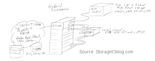
NVMe devices including NVM flash AIC flash will also find their way into storage systems and appliances as back-end storage, co-existing with SAS or SATA devices. Another emerging deployment configuration scenario is shared NVMe direct attached storage (DAS) with multiple server access via PCIe external storage with dual paths for resiliency.
Even though NVMe is a new protocol, it leverages existing skill sets. Anyone familiar with SAS/SCSI and AHCI/SATA storage devices will need little or no training to carry out and manage NVMe. Since NVMe-enabled storage appears to a host server or storage appliance as an LUN or volume, existing Windows, Linux and other OS or hypervisors tools can be used. On Windows, such as, other than going to the device manager to see what the device is and what controller it is attached to, it is no different from installing and using any other storage device. The experience on Linux is similar, particularly when using in-the-box drivers that ship with the OS. One minor Linux difference of note is that instead of seeing a /dev/sda device as an example, you might see a device name like /dev/nvme0n1 or /dev/nvme0n1p1 (with a partition).
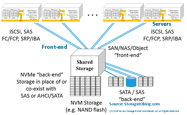
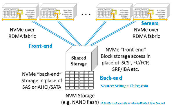
Keep in mind that NVMe like SAS can be used as a “back-end” access from servers (or storage systems) to a storage device or system. For example JBOD SSD drives (e.g. 8639), PCIe AiC or M.2 devices. NVMe can also like SAS be used as a “front-end” on storage systems or appliances in place of, or in addition to other access such as GbE based iSCSI, Fibre Channel, FCoE, InfiniBand, NAS or Object.
What this means is that NVMe can be implemented in a storage system or appliance on both the “front-end” e.g. server or host side as well as on the “back-end” e.g. device or drive side that is like SAS. Another similarity to SAS is that NVMe dual-pathing of devices, permitting system architects to design resiliency into their solutions. When the primary path fails, access to the storage device can be maintained with failover so that fast I/O operations can continue when using SAS and NVMe.
NVM connectivity options including NVMe
Various NVM NAND flash SSD devices and their connectivity including NVMe, M2, SATA and 12 Gbps SAS are shown in figure 6.
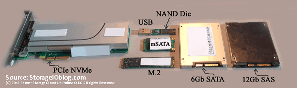
Figure 6 Various NVM flash SSDs (Via StorageIO Labs)
Left in figure 6 is an NAND flash NVMe PCIe AiC, top center is a USB thumb drive that has been opened up showing an NAND die (chip), middle center is a mSATA card, bottom center is an M.2 card, next on the right is a 2.5” 6 Gbps SATA device, and far fright is a 12 Gbps SAS device. Note that an M.2 card can be either an SATA or NVMe device depending on its internal controller that determines which host or server protocol device driver to use.
The role of PCIe has evolved over the years as has its performance and packaging form factors. Also, to add in card (AiC) slots, PCIe form factors also include M.2 small form factor that replaces legacy mini-PCIe cards. Another form factor is M.2 (aka Next Generation Form Factor or NGFF) that like other devices, can be an NVMe, or SATA device.
NGFF also known as 8639 or possibly 8637 (figure 7) can be used to support SATA as well as NVMe depending on the card device installed and host server driver support. There are various M.2 NGFF form factors including 2230, 2242, 2260 and 2280. There are also M.2 to regular physical SATA converter or adapter cards that are available enabling M.2 devices to attach to legacy SAS/SATA RAID adapters or HBAs.


Figure 7 PCIe NVMe 8639 Drive (Via StorageIO Labs)
On the left of figure 7 is a view towards the backplane of a storage enclosure in a server that supports SAS, SATA, and NVMe (e.g. 8639). On the right of figure 7 is the connector end of an 8639 NVM SSD showing addition pin connectors compared to an SAS or SATA device. Those extra pins give PCIe x4 connectivity to the NVMe devices. The 8639 drive connectors enable a device such as an NVM, or NAND flash SSD to share a common physical storage enclosure with SAS and SATA devices, including optional dual-pathing.
Where To Learn More
View additional NVMe, SSD, NVM, SCM, Data Infrastructure and related topics via the following links.
- NVMe overview and primer – Part I
- Part II – NVMe overview and primer (Different Configurations)
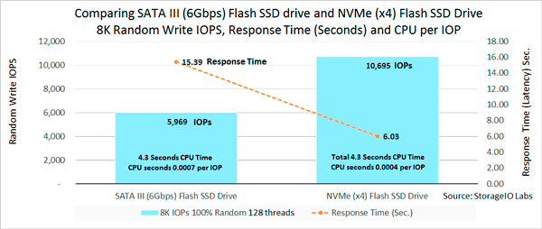
- Part III – NVMe overview and primer (Need for Performance Speed)
- Part IV – NVMe overview and primer (Where and How to use NVMe)
- Part V – NVMe overview and primer (Where to learn more, what this all means)
- PCIe Server I/O Fundamentals
- If NVMe is the answer, what are the questions?
- NVMe Wont Replace Flash By Itself
- Via Computerweekly – NVMe discussion: PCIe card vs U.2 and M.2
- Intel and Micron unveil new 3D XPoint Non Volatile Memory (NVM) for servers and storage
- Part II – Intel and Micron new 3D XPoint server and storage NVM
- Part III – 3D XPoint new server storage memory from Intel and Micron
- Server storage I/O benchmark tools, workload scripts and examples (Part I) and (Part II)
- Data Infrastructure Overview, Its Whats Inside of Data Centers
- All You Need To Know about Remote Office/Branch Office Data Protection Backup (free webinar with registration)
- Software Defined, Converged Infrastructure (CI), Hyper-Converged Infrastructure (HCI) resources
- The SSD Place (SSD, NVM, PM, SCM, Flash, NVMe, 3D XPoint, MRAM and related topics)
- The NVMe Place (NVMe related topics, trends, tools, technologies, tip resources)
- Data Protection Diaries (Archive, Backup/Restore, BC, BR, DR, HA, RAID/EC/LRC, Replication, Security)
- Software Defined Data Infrastructure Essentials (CRC Press 2017) including SDDC, Cloud, Container and more
- Various Data Infrastructure related events, webinars and other activities
Additional learning experiences along with common questions (and answers), as well as tips can be found in Software Defined Data Infrastructure Essentials book.

What This All Means
Be careful judging a device or component by its physical packaging or interface connection about what it is or is not. In figure 6.6 the device has SAS/SATA along with PCIe physical connections, yet it’s what’s inside (e.g. its controller) that determines if it is an SAS, SATA or NVMe enabled device. This also applies to HDDs and PCIe AiC devices, as well as I/O networking cards and adapters that may use common physical connectors, yet implement different protocols. For example, the SFF-8643 HD-Mini SAS internal connector is used for 12 Gbps SAS attachment as well as PCIe to devices such as 8630.
Depending on the type of device inserted, access can be via NVMe over PCIe x4, SAS (12 Gbps or 6Gb) or SATA. 8639 connector based enclosures have a physical connection with their backplanes to the individual drive connectors, as well as to PCIe, SAS, and SATA cards or connectors on the server motherboard or via PCIe riser slots.
While PCIe devices including AiC slot based, M.2 or 8639 can have common physical interfaces and lower level signaling, it’s the protocols, controllers, and drivers that determine how they get a software defined and used. Keep in mind that it’s not just the physical connector or interface that determines what a device is or how it is used, it’s also the protocol, command set, and controller and device drivers.
Continue reading about NVMe with Part V (Where to learn more, what this all means) in this five-part series, or jump to Part I, Part II or Part III.
Ok, nuff said, for now.
Gs
Greg Schulz – Microsoft MVP Cloud and Data Center Management, VMware vExpert 2010-2017 (vSAN and vCloud). Author of Software Defined Data Infrastructure Essentials (CRC Press), as well as Cloud and Virtual Data Storage Networking (CRC Press), The Green and Virtual Data Center (CRC Press), Resilient Storage Networks (Elsevier) and twitter @storageio. Courteous comments are welcome for consideration. First published on https://storageioblog.com any reproduction in whole, in part, with changes to content, without source attribution under title or without permission is forbidden.
All Comments, (C) and (TM) belong to their owners/posters, Other content (C) Copyright 2006-2026 Server StorageIO and UnlimitedIO. All Rights Reserved. StorageIO is a registered Trade Mark (TM) of Server StorageIO.


