ToE NVMeoF TCP Performance Line Boost Performance Reduce Costs

The ToE NVMeoF TCP Performance Line Boost Performance Reduce Costs

ToE NVMeoF TCP Performance Line Boost Performance Reduce Costs.

Yes, you read that correct; leverage TCP offload Engines (TOE) to boost the performance of TCP-based NVMeoF (e.g., NVMe over Fabrics) while reducing costs. Keep in mind that there is a difference between cutting costs (something that causes or moves problems and complexities elsewhere) and reducing and removing costs (e.g., finding, fixing, removing complexities).

Reducing or cutting costs can be easy by simply removing items for lower-priced items and introducing performance bottlenecks or some other compromise. Likewise, boosting performance can be addressed by throwing (deploying) more hardware (and or software) at the problem resulting in higher costs or some other compromise.

On the other hand, as mentioned above, finding, fixing, removing the complexity and overhead results in cost savings while doing the same work or enabling more work done via the same costs, maximizing hardware, software, and network costs. In other words, a better return on investment (ROI) and a lower total cost of ownership (TCO).

Software Defined Storage and Networks Need Hardware

With the continued shift towards software-defined data centers, software-defined data infrastructures, software-defined storage, software-defined networking, and software-defined everything, those all need something in common, and that is hardware-based compute processing.

In the case of software-defined storage, including standalone, shared fabric or networked-based, converged infrastructure (CI) or hyper-converged infrastructure (HCI) deployment models, there is the need for CPU compute, memory, and I/O, in addition to storage devices. This means that the software to create, manage, and perform storage tasks needs to run on a server’s CPU, along with I/O networking software stacks.

However, it should be evident that sometimes the obvious needs to be restarted, which is that software-defined anything requires hardware somewhere in the solution stack. Likewise, depending on how the software is implemented, it may require more hardware resources, including server compute, memory, I/O, and network and storage capabilities.

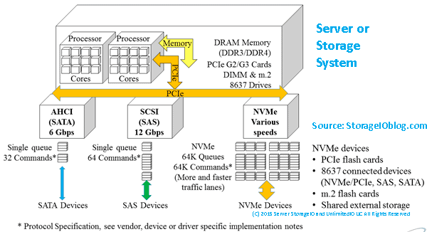
Keep in mind that networking stacks, including upper and lower-level protocols and interfaces, leverage software to implement their functionality. Therefore, the value proposition of using standard networks such as Ethernet and TCP is the ability to leverage lower-cost network interface cards (or chips), also known as NICs combined with server-based software stacks.

On the one hand, costs can be reduced by using less expensive NICs and using the generally available server CPU compute capabilities to run the TCP and other networking stack software. On systems with a lower application or other software performance demands, this can work out ok. However, for workloads and systems using software-defined storage and other applications that compete for server resources (CPU, memory, I/O), this can result in performance bottlenecks and problems.

Many Server Storage I/O Networking Bottlenecks Are CPU Problems

There is a classic saying that the best I/O is the one that you do not have to do. Likewise, the second-best I/O is the one with the most negligible overhead (and cost) as well as best performance. Another saying is that many application, database, server, and storage I/O problems are actually due to CPU bottlenecks. Fast storage devices need fast applications on fast servers with fast networks. This means finding and removing blockages, including offloading server CPU from performing network I/O processing using TOEs.

Wait a minute, isn’t the value proposition of using software-defined storage or networking to use low-cost general-purpose servers instead of more expensive hardware devices? With some caveats, Yup understands how much server CPU us being used to run the software-defined storage and software stacks and handle upper-level functionality. To support higher performance or larger workloads can be putting in more extensive (scale-up) and more (scale-out) servers and their increased connectivity and management overhead.

This is where the TOEs come into play by leveraging the best of both worlds to run software-defined storage (and networking) stacks, and other software and applications on general-purpose compute servers. The benefit is the TCP network I/O processing gets offloaded from the server CPU to the TOE, thereby freeing up the server CPU to do more work or enabling a smaller, lower-cost CPU to be used.

After all, many servers, storage, and I/O networking problems are often server CPU problems. An example of this is running the TCP networking software stack using CPU cycles on a host server that competes with the other software and applications. In addition, as an application does more I/O, for example, issuing reads and write requests to network and fabric-based storage, the server’s CPUs are also becoming busier with more overhead of running the lower-layer TCP and networking stack.

The result is server resources (CPU, memory) are running at higher utilization; however, there is more overhead. Higher resource utilization with low or no overhead, low latency, and high productivity are good things resulting in lower cost per work done. On the other hand, high CPU utilization, server operating system or kernel mode overhead, poor latency, and low productivity are not good things resulting in host per work done.

This means there is a loss of productivity as more time is spent waiting, and the cost to do a unit of work, for example, an I/O or transaction, increases (there is more overhead). Thus, offload engines (chips, cards, adapters) come into play to shift some software processing from the server CPU to a specialized processor. The result is lower server CPU overhead leaving more server resources for the main application or software-defined storage (and networking) while boosting performance and lowering overall costs.

Graphics, Compute, Network, TCP Offload Engines

Offload engines are not new, they have been around for a while, and in some cases, more common than some realize going by different names. For example, graphical Processing Units (GPUs) are used for offloading graphic and compute-intensive tasks to special chips and adapter cards. Other examples of offload processors include networks such as TCP Offload Engine (TOE), compression, and storage processing, among others.

The basic premise of offload engines is to move or shift processing of specific functions from having their software running on a general-purpose server CPU to a specialized processor (ASIC, FPGA, adapter, or mezzanine card). By moving the processing of functions to the offload or unique processing device, performance can be boosted while freeing up a server’s primary processor (CPU) to do other useful (and productive) work.

There is a cost associated with leveraging offloads and specialized processors; however, the business benefit should be offset by reducing primary server compute expenses or doing more work with available resources and driving network bandwidth line rates performance. The above should result in a net TCO reduction and boost your ROI for a given system or bill of material, including hardware, software, networking, and management.

Cloud File Data Storage Consolidation and Economic Comparison Model

Fast Storage Needs Fast Servers and I/O Networks

Ethernet network TOEs became popular in the industry back in the early 2000s, focusing on networked storage and storage networks that relied on TCP (e.g., iSCSI).

Fast forward to today, and there is continued use of networked (ok, fabric) storage over various interfaces, including Ethernet supporting different protocols. One of those protocols is NVMe in NVMe over Fabrics (NVMeoF) using TCP and underlying Ethernet-based networks for accessing fast Solid State Devices (SSDs).

Chelsio Communications T6 TOE for NVMeoF

An example of server storage I/O network TOEs, including those to support NVMeoF, are those from Chelsio Communications, such as the T6 25/100Gb devices. Chelsio announced today server storage I/O benchmark proof points for TCP based NVMe over Fabric (NVMeoF) TOE accelerated performance. StorageIO had the opportunity to look at the performance-boosting ability and CPU savings benefit of the Chelsio T6 prior to todays announcement.

After reviewing and validating the Chelsio proof points, test methodology, and results, it is clear that the T6 TOE enabled solution boosts server storage I/O performance while reducing host server CPU usage. The Chelsio T6 solution combined with Storage Performance Development Kit (SPDK) software, provides local-like performance of network fabric distributed NVMe (using TCP based NVMeoF) attached SSD storage while reducing host server CPU consumption.

“Boosting application performance, efficiency, and effectiveness of server CPUs are key priorities for legacy and software defined datacenter environments,” said Greg Schulz, Sr. Analyst Server Storage. “The Chelsio NVMe over Fabrics 100GbE NVMe/TCP (TOE) demonstration provides solid proof of how high-performance NVMe SSDs can help datacenters boost performance and productivity, while getting the best return on investment of datacenter infrastructure assets, not to mention optimize cost-of-ownership at the same time. It’s like getting a three for one bonus value from your server CPUs, your network, and your application perform better, now that’s a trifecta!”

You can read more about the technical and business benefits of the Chelsio T6 TOE enabled solution along with associated proof points (benchmarks) in the PDF white paper found here and their Press Release here. Note that the best measure, benchmark, proof point, or test is your application and workload, so contact Chelsio to arrange an evaluation of the T6 using your workload, software, and platform.

Where to learn more

Learn more about TOE, server, compute, GPU, ASIC, FPGA, storage, I/O networking, TCP, data infrastructure and software defined and related topics, trends, techniques, tools via the following links:

Chelsio Communications T6 Performance Press Release (PDF)
Chelsio Communications T6 TOE White Paper (PDF)
Application Data Value Characteristics Everything Is Not the Same
PACE your Infrastructure decision-making, it’s about application requirements
Data Infrastructure Server Storage I/O Tradecraft Trends
Data Infrastructure Overview, Its What’s Inside of Data Centers
Data Infrastructure Management (Insight and Strategies)
Hyper-V and Windows Server 2025 Enhancements

Additional learning experiences along with common questions (and answers), as well as tips can be found in Software Defined Data Infrastructure Essentials book.

Software Defined Data Infrastructure Essentials Book SDDC

What this all means

The large superscalar web services and other large environments leverage offload engines and specialized processing technologies (chips, ASICs, FPGAs, GPUs, adapters) to boost performance while reducing server compute costs or getting more value out of a given server platform. If it works for the large superscalars, it can also work for your environment or your software-defined platform.

The benefits are reducing the number and cost of your software-defined platform bill of materials (BoM). Another benefit is to free up server CPU cycles to run your storage or network or other software to get more performance and work done. Yet another benefit is the ability to further stretch your software license investments, getting more work done per software license unit.

Have a look at the Chelsio Communications T6 line of TOE for NVMeoF and other workloads to boost performance, reduce CPU usage and lower costs. See for yourself The TOE NVMeoF TCP Performance Line Boost Performance Reduce Costs benefit.

Ok, nuff said, for now.

Cheers GS

Greg Schulz – Microsoft MVP Cloud and Data Center Management, previous 10 time VMware vExpert. Author of Software Defined Data Infrastructure Essentials (CRC Press), Data Infrastructure Management (CRC Press), as well as Cloud and Virtual Data Storage Networking (CRC Press), The Green and Virtual Data Center (CRC Press), Resilient Storage Networks (Elsevier) and twitter @storageio. Courteous comments are welcome for consideration. First published on https://storageioblog.com any reproduction in whole, in part, with changes to content, without source attribution under title or without permission is forbidden.

All Comments, (C) and (TM) belong to their owners/posters, Other content (C) Copyright 2006-2024 Server StorageIO and UnlimitedIO. All Rights Reserved. StorageIO is a registered Trade Mark (TM) of Server StorageIO.

PCIe Fundamentals Server Storage I/O Network Essentials

Updated 8/31/19

PCIe Fundamentals Server Storage I/O Network Essentials

PCIe fundamentals data infrastructure trends

This piece looks at PCIe Fundamentals topics for server, storage, I/O network data infrastructure environments. Peripheral Computer Interconnect (PCI) Express aka PCIe is a Server, Storage, I/O networking fundamentals component. This post is an excerpt from chapter 4 (Chapter 4: Servers: Physical, Virtual, Cloud, and Containers) of my new book Software Defined Data Infrastructure Essentials – Cloud, Converged and Virtual Fundamental Server Storage I/O Tradecraft (CRC Press 2017) Available via Amazon.com and other global venues. In this post, we look various PCIe fundamentals to learn and expand or refresh your server, storage, and I/O and networking tradecraft skills experience.

PCIe fundamentals Server Storage I/O Fundamentals

PCIe fundamental common server I/O component

Common to all servers is some form of a main system board, which can range from a few square meters in supercomputers, data center rack, tower, and micro towers converged or standalone, to small Intel NUC (Next Unit of Compute), MSI and Kepler-47 footprint, or Raspberry Pi-type desktop servers and laptops. Likewise, PCIe is commonly found in storage and networking systems, appliances among other devices.

For example, a blade server will have multiple server blades or modules, each with its motherboard, which shares a common back plane for connectivity. Another variation is a large server such as an IBM “Z” mainframe, Cray, or another supercomputer that consists of many specialized boards that function similar to a smaller-sized motherboard on a larger scale.

Some motherboards also have mezzanine or daughter boards for attachment of additional I/O networking or specialized devices. The following figure shows a generic example of a two-socket, with eight-memory-channel-type server architecture.

PCIe fundamentals SDDC, SDI, SDDI Server fundamentals
Generic computer server hardware architecture. Source: Software Defined Data Infrastructure Essentials (CRC Press 2017)

The above figure shows several PCIe, USB, SAS, SATA, 10 GbE LAN, and other I/O ports. Different servers will have various combinations of processor, and Dual Inline Memory Module (DIMM) Dynamic RAM (DRAM) sockets along with other features. What will also vary are the type and some I/O and storage expansion ports, power and cooling, along with management tools or included software.

PCIe, Including Mini-PCIe, NVMe, U.2, M.2, and GPU

At the heart of many servers I/O and connectivity solutions are the PCIe industry-standard interface (see PCIsig.com). PCIe is used to communicate with CPUs and the outside world of I/O networking devices. The importance of a faster and more efficient PCIe bus is to support more data moving in and out of servers while accessing fast external networks and storage.

For example, a server with a 40-GbE NIC or adapter would have to have a PCIe port capable of 5 GB per second. If multiple 40-GbE ports are attached to a server, you can see where the need for faster PCIe interfaces come into play.

As more VM are consolidated onto PM, as applications place more performance demand either regarding bandwidth or activity (IOPS, frames, or packets) per second, more 10-GbE adapters will be needed until the price of 40-GbE (also 25, 50 or 100 Gbe) becomes affordable. It is not if, but rather when you will grow into the performance needs on either a bandwidth/throughput basis or to support more activity and lower latency per interface.

PCIe is a serial interface specified for how servers communicate between CPUs, memory, and motherboard-mounted as well as AiC devices. This communication includes support attachment of onboard and host bus adapter (HBA) server storage I/O networking devices such as Ethernet, Fibre Channel, InfiniBand, RapidIO, NVMe (cards, drives, and fabrics), SAS, and SATA, among other interfaces.

In addition to supporting attachment of traditional LAN, SAN, MAN, and WAN devices, PCIe is also used for attaching GPU and video cards to servers. Traditionally, PCIe has been focused on being used inside of a given server chassis. Today, however, PCIe is being deployed on servers spanning nodes in dual, quad, or CiB, CI, and HCI or Software Defined Storage (SDS) deployments. Another variation of PCIe today is that multiple servers in the same rack or proximity can attach to shared devices such as storage via PCIe switches.

PCIe components (hardware and software) include:

  • Hardware chipsets, cabling, connectors, endpoints, and adapters
  • Root complex and switches, risers, extenders, retimers, and repeaters
  • Software drivers, BIOS, and management tools
  • HBAs, RAID, SSD, drives, GPU, and other AiC devices
  • Mezzanine, mini-PCIe, M.2, NVMe U.2 (8639 drive form factor)

There are many different implementations of PCIe, corresponding to generations representing speed improvements as well as physical packing options. PCIe can be deployed in various topologies, including a traditional model where an AiC such as GbE or Fibre Channel HBA connects the server to a network or storage device.

Another variation is for a server to connect to a PCIe switch, or in a shared PCIe configuration between two or more servers. In addition to different generations and topologies, there are also various PCIe form factors and physical connectors (see the following figure), ranging from AiC of various length and height, as well as M.2 small-form-factor devices and U.2 (8639) drive form-factor device for NVMe, among others.

Note that the presence of M.2 does not guarantee PCIe NVMe, as it also supports SATA.

Likewise, different NVMe devices run at various PCIe speeds based on the number of lanes. For example, in the following figure, the U.2 (8639) device (looks like a SAS device) shown is a PCIe x4.

SDDC, SDI, SDDI PCIe NVMe U.2 8639 drive fundamentals
PCIe devices NVMe U.2, M.2, and NVMe AiC. (Source: StorageIO Labs.)

PCIe leverages multiple serial unidirectional point-to-point links, known as lanes, compared to traditional PCI, which used a parallel bus design. PCIe interfaces can have one (x1), four (x4), eight (x8), sixteen (x16), or thirty-two (x32) lanes for data movement. Those PCIe lanes can be full-duplex, meaning data is sent and received at the same time, providing improved effective performance.

PCIe cards are upward-compatible, meaning that an x4 can work in an x8, an x8 in an x16, and so forth. Note, however, that the cards will not perform any faster than their specified speed; an x4 in an x8 slot will only run at x8. PCIe cards can also have single, dual, or multiple external ports and interfaces. Also, note that there are still some motherboards with legacy PCI slots that are not interoperable with PCIe cards and vice versa.

Note that PCIe cards and slots can be mechanically x1, x4, x8, x16, or x32, yet electrically (or signal) wired to a slower speed, based on the type and capabilities of the processor sockets and corresponding chipsets being used. For example, you can have a PCIe x16 slot (mechanical) that is wired for x8, which means it will only run at x8 speed.

In addition to the differences between electrical and mechanical slots, also pay attention to what generation the PCIe slots are, such as Gen 2 or Gen 3 or higher. Also, some motherboards or servers will advertise multiple PCIe slots, but those are only active with a second or additional processor socket occupied by a CPU. For example, a PCIe card that has dual x4 external PCIe ports requiring full PCIe bandwidth will need at least PCIe x8 attachment in the server slot. In other words, for full performance, the external ports on a PCIe card or device need to match the external electrical and mechanical card type and vice versa.

Recall big “B” as in Bytes vs. little “b” as in bits; for example, a PCIe Gen 3 x4 electrical could provide up to 4 GB/s bandwidth (your mileage and performance will vary), which translates to 8 × 4 GB or 32 Gbits/s. In the following table below, there is a mix of Big “B” Bytes per second and small “b” bits per second.

Each generation of PCIe has improved on the previous one by increasing the effective speed of the links. Some of the speed improvements have come from faster clock rates while implementing lower overhead encoding (e.g., from 8 b/10 b to 128 b/130 b).

For example, PCIe Gen 3 raw bit or line rate is 8 GT/s or 8 Gbps or about 2 GBps by using a 128 b/130 b encoding scheme that is very efficient compared to PCIe Gen 2 or Gen 1, which used an 8 b/10 b encoding scheme. With 8 b/10 b, there is a 20% overhead vs. a 1.5% overhead with 128 b/130 b (i.e., of 130 bits sent, 128 bits contain data, and 2 bits are for overhead).

PCIe Gen 1

PCIe Gen 2

PCIe Gen 3

PCIe Gen 4

PCIe Gen 5

Raw bit rate

2.5 GT/s

5 GT/s

8 GT/s

16 GT/s

32 GT/s

Encoding

8 b/10 b

8 b/10 b

128 b/130 b

128 b/130 b

128 b/130 b

x1 Lane bandwidth

2 Gb/s

4 Gb/s

8 Gb/s

16 Gb/s

32 Gb/s

x1 Single lane (one-way)

~250 MB/s

~500 MB/s

~1 GB/s

~2 GB/s

~4GB/s

x16 Full duplex (both ways)

~8 GB/s

~16 GB/s

~32 GB/s

~64 GB/s

~128 GB/s

Above Table: PCIe Generation and Sample Lane Comparison

Note that PCIe Gen 3 is the currently generally available shipping technology with PCIe Gen 4 appearing in the not so distant future, with PCIe Gen 5 in the wings appearing a few more years down the road.

By contrast, older generations of Fibre Channel and Ethernet also used 8 b/10 b, having switched over to 64 b/66 b encoding with 10 Gb and higher. PCIe, like other serial interfaces and protocols, can support full-duplex mode, meaning that data can be sent and received concurrently.

PCIe Bit Rate, Encoding, Giga Transfers, and Bandwidth

Let’s clarify something about data transfer or movement both internal and external to a server. At the core of a server, there is data movement within the sockets of the processors and its cores, as well as between memory and other devices (internal and external). For example, the QPI bus is used for moving data between some Intel processors whose performance is specified in giga transfers (GT).

PCIe is used for moving data between processors, memory, and other devices, including internal and external facing devices. Devices include host bus adapters (HBAs), host channel adapters (HCAs), converged network adapters (CNAs), network interface cards (NICs) or RAID cards, and others. PCIe performance is specified in multiple ways, given that it has a server processor focus which involves GT for raw bit rate as well as effective bandwidth per lane.

Note to keep in perspective PCIe mechanical as well as electrical lanes in that a card or slot may be advertised as say x8 mechanical (e.g., its physical slot form factor) yet only be x4 electrical (how many of those lanes are used or enabled). Also in the case of an adapter that has two or more ports, if the device is advertised as x8 does that mean it is x8 per port or x4 per port with an x8 connection to the PCIe bus.

Effective bandwidth per lane can be specified as half- or full-duplex (data moving in one or both directions for send and receive). Also, effective bandwidth can be specified as a single lane (x1), four lanes (x4), eight lanes (x8), sixteen lanes (x16), or 32 lanes (x32), as shown in the above table. The difference in speed or bits moved per second between the raw bit or line rate, and the effective bandwidth per lane in a single direction (i.e., half-duplex) is the encoding that is common to all serial data transmissions.

When data gets transmitted, the serializer/deserializer, or serdes, convert the bytes into a bit stream via encoding. There are different types of encoding, ranging from 8 b/10 b to 64 b/66 b and 128 b//130 b, shown in the following table.

Single 1542-byte frame

64 × 1542-byte frames

Encoding Scheme

Overhead

Data Bits

Encoding Bits

Bits Transmitted

Data Bits

Encoding Bits

Bits Transferred

8 b/10 b

20%

12,336

3,084

15,420

789,504

197,376

986,880

64 b/66 b

3%

12,336

386

12,738

789,504

24,672

814,176

128 b/130 b

1.5%

12,336

194

12,610

789,504

12,336

801,840

Above Table: Low-Level Serial Encoding Data Transmit Efficiency

In these encoding schemes, the smaller number represents the amount of data being sent, and the difference is the overhead. Note that this is different yet related to what occurs at a higher level with the various network protocols such as TCP/IP (IP). With IP, there is a data payload plus addressing and other integrity and management features in a given packet or frame.

The 8-b/10-b, 64-b/66-b or 128-b/130-b encoding is at the lower physical layer. Thus, a small change there has a big impact and benefit when optimized. Table 4.2 shows comparisons of various encoding schemes using the example of moving a single 1542-byte packet or frame, as well as sending (or receiving) 64 packets or frames that are 1542 bytes in size.

Why 1542? That is a standard IP packet including data and protocol framing without using jumbo frames (MTU or maximum transmission units).

What does this have to do with PCIe? GbE, 10-GbE, 40-GbE, and other physical interfaces that are used for moving TCP/IP packets and frames interface with servers via PCIe.

This encoding is important as part of server storage I/O tradecraft regarding understanding the impact of performance and network or resource usage. It also means understanding why there are fewer bits per second of effective bandwidth (independent of compression or deduplication) vs. line rate in either half- or full-duplex mode.

Another item to note is that looking at encoding such as the example given in the above table shows how a relatively small change at a large scale can have a big effective impact benefit. If the bits and bytes encoding efficiency and effectiveness scenario in Table 4.2 do not make sense, then try imagining 13 MINI Cooper automobiles each with eight people in it (yes, that would be a tight fit) end to end on the same road.

Now imagine a large bus that takes up much less length on the road than the 13 MINI Coopers. The bus holds 128 people, who would still be crowded but nowhere near as cramped as eight people in a MINI, plus 24 additional people can be carried on the bus. That is an example of applying basic 8-b/10-b encoding (the MINI) vs. applying 128-b/130-b encoding (the bus) and is also similar to PCIe G3 and G4, which use 128-b/130-b encoding for data movement.

PCIe Topologies

The basic PCIe topology configuration has one or more devices attached to the root complex shown in the following figure via an AiC or onboard device connector. Examples of AiC and motherboard-mounted devices that attach to PCIe root include LAN or SAN HBA, networking, RAID, GPU, NVM or SSD, among others. At system start-up, the server initializes the PCIe bus and enumerates the devices found with their addresses.

PCIe devices attach (shown in the following figure) to a bus that communicates with the root complex that connects with processor CPUs and memory. At the other end of a PCIe device is an end-point target, a PCIe switch that in turn has end-point targets attached. From a software standpoint, hypervisor or operating system device drivers communicate with the PCI devices that in turn send or receive data or perform other functions.

SDDC, SDI, SDDI PCIe fundamentals
Basic PCIe root complex with a PCIe switch or expander.

Note that in addition to PCIe AiC such as HBAs, GPU, and NVM SSD, among others that install into PCIe slots, servers also have converged storage or disk drive enclosures that support a mix of SAS, SATA, and PCIe. These enclosure backplanes have a connector that attaches to a SAS or SATA onboard port, or a RAID card, as well as to a PCIe riser card or motherboard connector. Depending on what type of drive is installed in the connector, either the SAS, SATA, or NVMe (AiC, U.2, and M2) using PCIe communication paths are used.

In addition to traditional and switched PCIe, using PCIe switches as well as nontransparent bridging (NTB), various other configurations can be deployed. These include server to server for clustering, failover, or device sharing as well as fabrics. Note that this also means that while traditionally found inside a server, PCIe can today use an extender, retimer, and repeaters extended across servers within a rack or cabinet.

A nontransparent bridge (NTB) is a point-to-point connection between two PCIe-based systems that provide electrical isolation yet functions as a transport bridge between two different address domains. Hosts on either side of the NTB see their respective memory or I/O address space. The NTB presents an endpoint exposed to the local system where writes are mirrored to memory on the remote system to allow the systems to communicate and share devices using associated device drivers. For example, in the following figure, two servers, each with a unique PCIe root complex, address, and memory map, are shown using NTB to any communication between the systems while maintaining data integrity.

SDDC, SDI, SDDI PCIe two server fundamentals
PCIe dual server example using NTB along with switches.

General PCIe considerations (slots and devices) include:

  • Power consumption (and heat dissipation)
  • Physical and software plug-and-play (good interoperability)
  • Drivers (in-the-box, built into the OS, or add-in)
  • BIOS, UEFI, and firmware being current versions
  • Power draw per card or adapters
  • Type of processor, socket, and support chip (if not an onboard processor)
  • Electrical signal (lanes) and mechanical form factor per slot
  • Nontransparent bridge and root port (RP)
  • PCI multi-root (MR), single-root (SR), and hot plug
  • PCIe expansion chassis (internal or external)
  • External PCIe shared storage

Various operating system and hypervisor commands are available for viewing and managing PCIe devices. For example, on Linux, the “lspci” and “lshw–c pci” commands displays PCIe devices and associated information. On a VMware ESXi host, the “esxcli hardware pci list” command will show various PCIe devices and information, while on Microsoft Windows systems, “device manager” (GUI) or “devcon” (command line) will show similar information.

Who Are Some PCIe Fundamentals Vendors and Service Providers

While not an exhaustive list, here is a sampling of some vendors and service providers involved in various ways with PCIe from solutions to components to services to trade groups include Amphenol (connectors and cables), AWS (cloud data infrastructure services), Broadcom (PCIe components), Cisco (servers), DataOn (servers), Dell EMC (servers, storage, software), E8 (storage software), Excelero (storage software), HPE (storage, servers), Huawei (storage, servers), IBM, Intel (storage, servers, adapters), Keysight (test equipment and tools).

Others include Lenovo (servers), Liqid (composable data infrastructure), Mellanox (server and storage adapters), Micron (storage devices), Microsemi (PCIe components), Microsoft (Cloud and Software including S2D), Molex (connectors, cables), NetApp, NVMexpress.org (NVM Express trade group organizations), Open Compute Project (server, storage, I/O network industry group), Oracle, PCISIG (PCIe industry trade group), Samsung (storage devices), ScaleMP (composable data infrastructure), Seagate (storage devices), SNIA (industry trade group), Supermicro (servers), Tidal (composable data infrastructure), Vantar (formerly known as HDS), VMware (Software including vSAN), and WD among others.

Where To Learn More

Learn more about related technology, trends, tools, techniques, and tips with the following links.

Additional learning experiences along with common questions (and answers), as well as tips can be found in Software Defined Data Infrastructure Essentials book.

Software Defined Data Infrastructure Essentials Book SDDC

What This All Means

PCIe fundamentals are resources for building legacy and software-defined data infrastructures (SDDI), software-defined infrastructures (SDI), data centers and other deployments from laptop to large scale, hyper-scale cloud service providers. Learn more about Servers: Physical, Virtual, Cloud, and Containers in chapter 4 of my new book Software Defined Data Infrastructure Essentials (CRC Press 2017) Available via Amazon.com and other global venues. Meanwhile, PCIe fundamentals continues to evolve as a Server, Storage, I/O networking fundamental component.

Ok, nuff said, for now.
Gs

Greg Schulz – Microsoft MVP Cloud and Data Center Management, VMware vExpert 2010-2017 (vSAN and vCloud). Author of Software Defined Data Infrastructure Essentials (CRC Press), as well as Cloud and Virtual Data Storage Networking (CRC Press), The Green and Virtual Data Center (CRC Press), Resilient Storage Networks (Elsevier) and twitter @storageio.

Courteous comments are welcome for consideration. First published on https://storageioblog.com any reproduction in whole, in part, with changes to content, without source attribution under title or without permission is forbidden.

All Comments, (C) and (TM) belong to their owners/posters, Other content (C) Copyright 2006-2023 Server StorageIO(R) and UnlimitedIO. All Rights Reserved.